Portfolio

HELMS Project - Wireline Service Group (WSG)
Brief Overview
HELMS is an advanced robotic system designed for automated pick-and-place operations in geophysical surveying at mineral exploration sites in Western Australia. By integrating robust mechanical engineering with real-time software controls and cutting-edge robotics, HELMS achieves exceptional precision, enhanced safety, and significant efficiency gains in challenging mining environments.
My Contributions
Mechanical Design & Analysis
- Designed and modeled robot links and joints, leveraging finite element analysis (FEA) to ensure robust structural integrity
- Utilized genetic algorithms to optimize torque calculations and refine gas spring placement for enhanced performance
- Led the mechanical design and integration of robotic joints into the system’s structure, ensuring seamless functionality
Motion Planning & Control
- Derived forward and inverse kinematics for precise motion control
- Developed real-time motion control logic in C++ and ROS2
- Employed CoDeSys for PLC-based coordination and shared memory mechanisms for interprocess communication
System Architecture
- Integrated Kollmorgen AKD2G servo drives, Schunk grippers, and Thomson linear actuators
- Synchronized all actuators via Linux EtherCAT for high-speed, real-time performance
- Built a scripting parser enabling dynamic task execution without recompilation
Complex Mechanism Coordination
- Orchestrated dual linear actuators (e.g., opening a 3-meter-long toolbox lid) with real-time force distribution and fault handling
- Developed stabilizer leg control using ROS2 algorithms for dynamic pressure management
- Implemented a vertical alignment algorithm (kinematics + inclinometer feedback) for precise tool placement into logging holes
Sensor Integration & Safety
- Incorporated ZED and OAK cameras for depth sensing and geofencing
- Developed sensor-based fault detection to enhance operational safety
- Provided HMI control for intuitive user interaction
Key Technologies
- Software & Control: C++, ROS2, CoDeSys, shared memory, Linux EtherCAT, CANOpen
- Mechanical Tools: SolidWorks (design & FEA), genetic algorithms (optimization)
- Hardware Components: Kollmorgen AKD2G servo drives, Schunk grippers, Thomson linear actuators
- Sensors & Vision: ZED and OAK cameras for depth sensing and geofencing
Motivation & Goals
- Streamline large-scale, repetitive tasks in geophysical surveying
- Achieve robust, real-time coordination across complex mechanical subsystems
- Increase safety, precision, and flexibility in harsh operational environments
Outcome
- Created a reliable, high-performance robotic truck that efficiently handles geophysical survey tools
- Improved safety and operational efficiency by automating complex mechanical tasks and integrating sensor-based fault detection
- Showcased the seamless integration of mechanical engineering, real-time software development, and advanced robotics within a single, unified system.
Laser Tracker - Fast Brick Robotics (FBR)
Visualization & HMI Integration
- Developed robotic system visualization using Three.js.
- Integrated TwinCAT TE2000 with JavaScript and Three.js for real-time monitoring and troubleshooting through an HMI interface.
Laser Tracker Integration & Data Logging
- Integrated laser tracker data collection into TwinCAT PLC.
- Implemented real-time logging to enhance system diagnostics and performance analysis.
Accuracy & Repeatability Analysis
- Conducted accuracy and repeatability tests for laser tracker technologies.
- Analyzed measurement precision to improve robotic system performance.
Python PyBullet & URDF Visualization
- Integrated PyBullet and URDF visualization using live data from TwinCAT PLC via ADS APIs.
- Enabled real-time robotic simulation and analysis for system optimization.
Advanced Geometric Error Modeling & PyTorch Implementation
- Developed and refined geometric error models using PyTorch to address mechanical inaccuracies in laser tracker.
- Employed systematic training and validation workflows to ensure robust generalization while avoiding overfitting.
- Optimized the models via iterative data analysis and real-world testing, improving overall accuracy and system reliability.
Control and Data System Commissioning - Gingin High Optical Power Facility (HOPF)
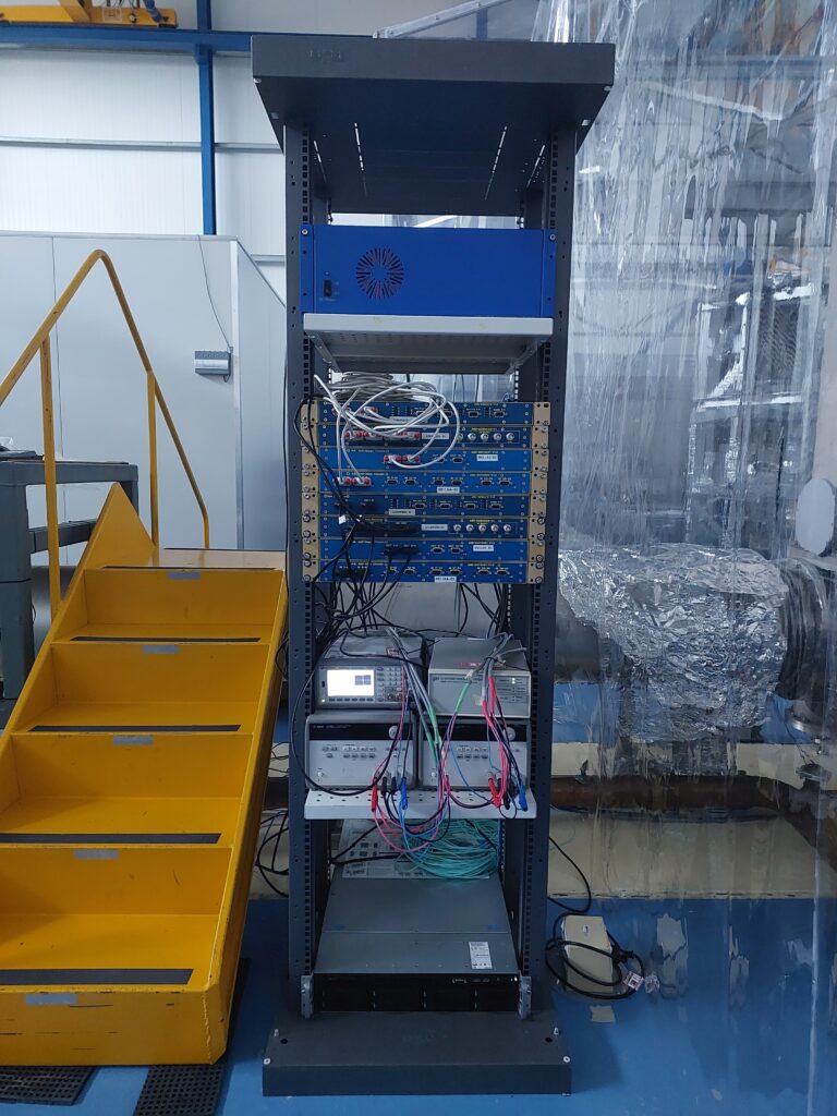
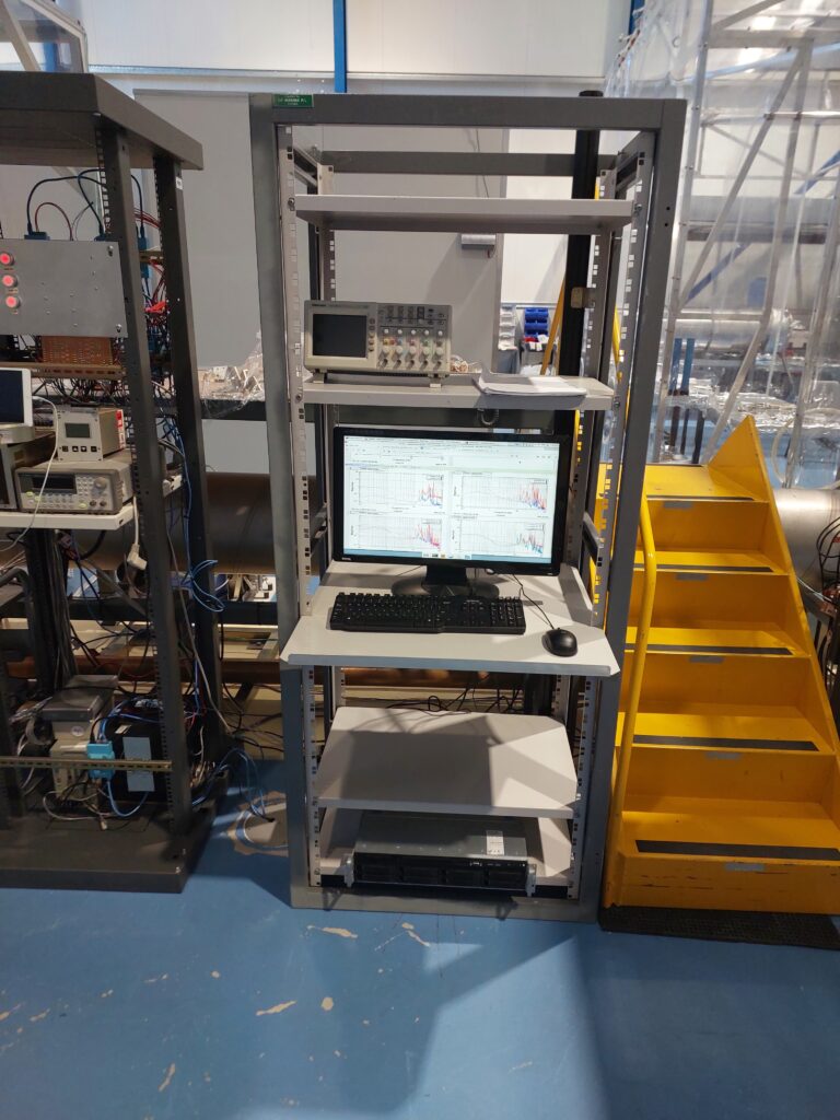
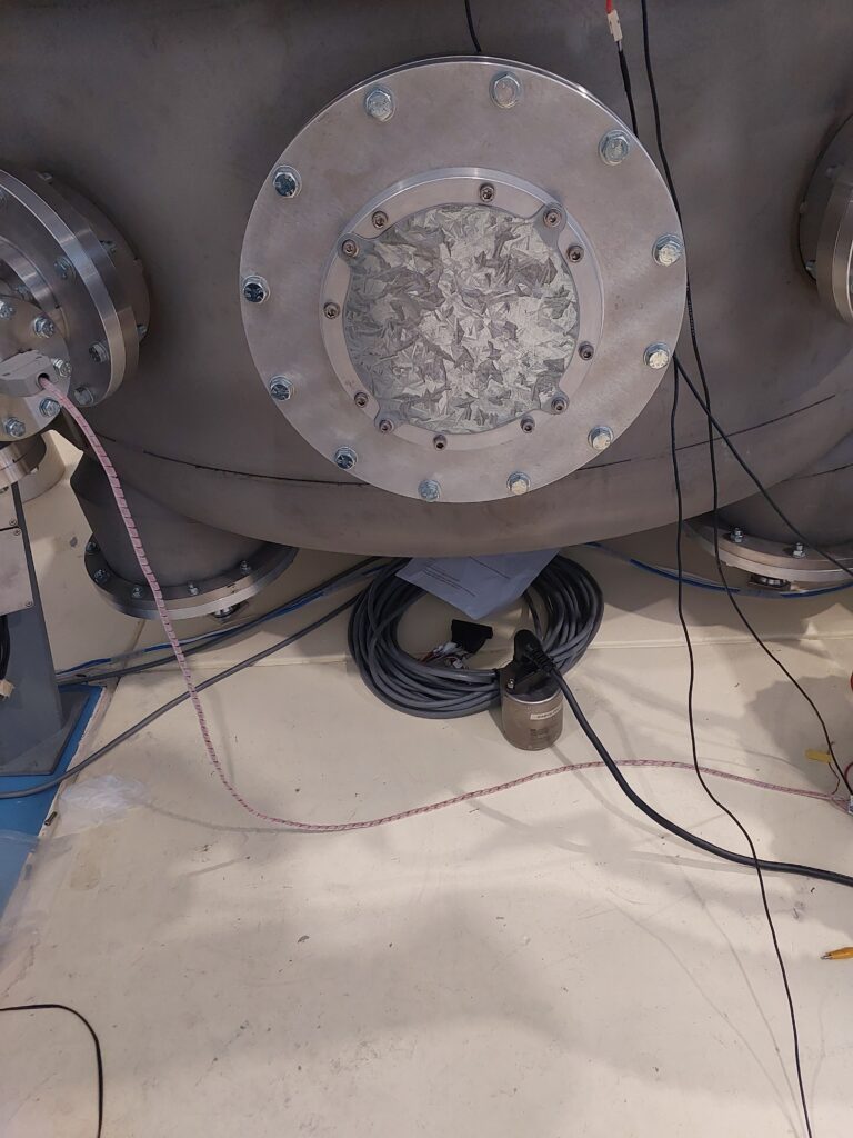
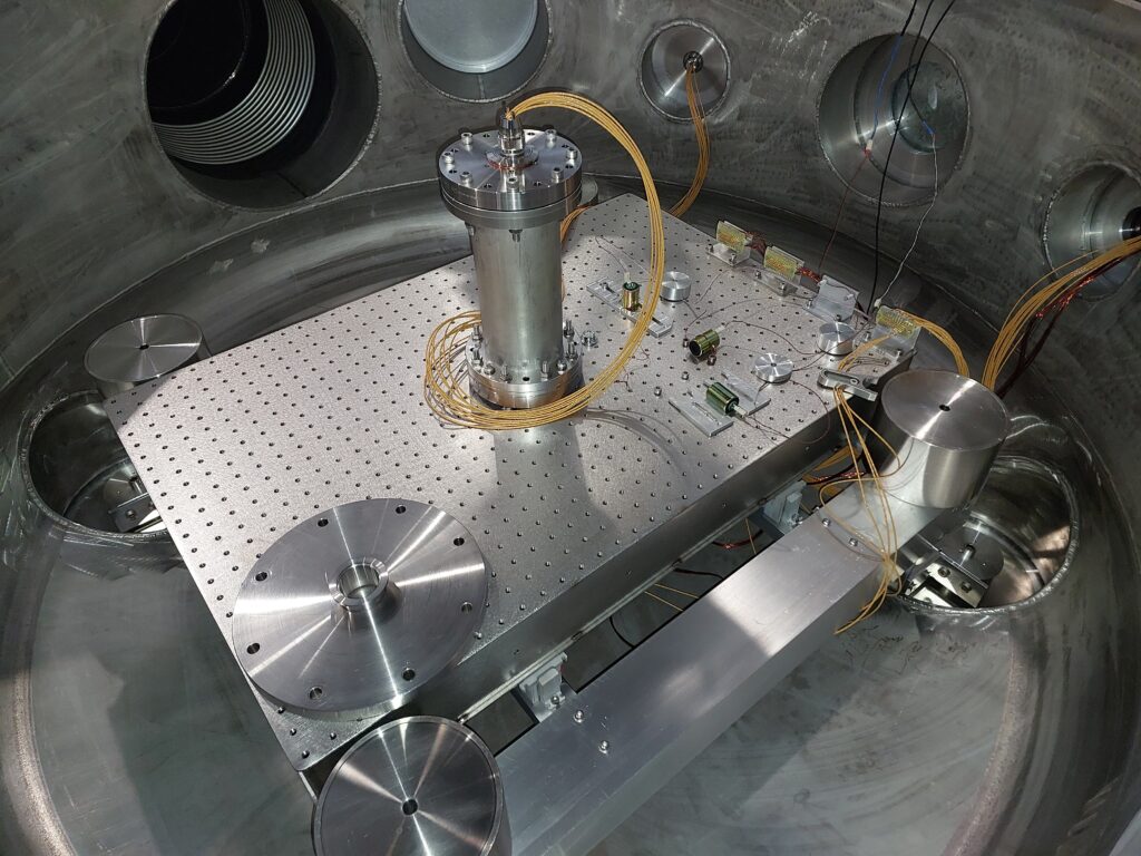
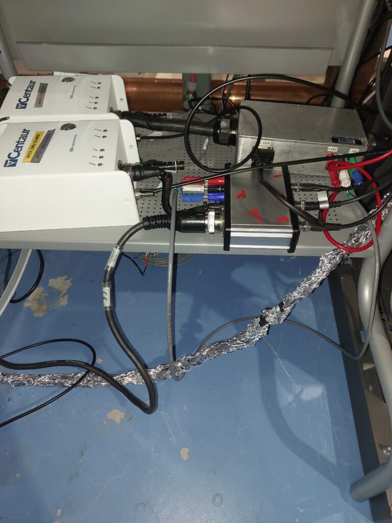
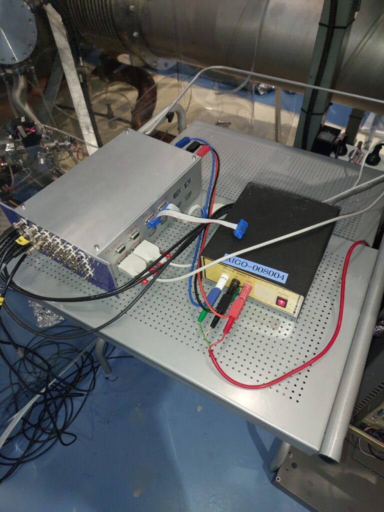
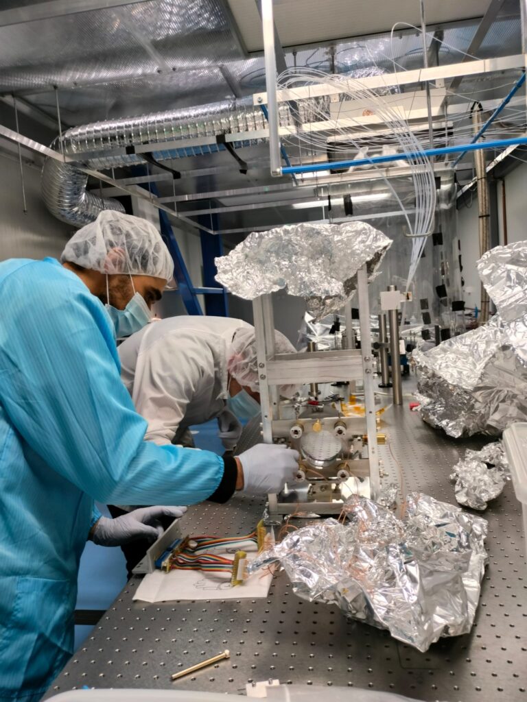
I commissioned the LIGO Control and Data System (CDS) for the first time in the University of Western Australis High Optical Power Facility. I undertook several key tasks to ensure its smooth operation and functionality. First, I configured a high-performance server as the front-end server for the LIGO CDS, establishing a fiber optic link to the expansion box for real-time data acquisition of analog inputs and outputs. Additionally, I installed the real-time Linux kernel for the CDS and set up essential CDS tools such as ndscope, diagui, and local DC to broadcast CDS channels on the local network. To facilitate development and testing, I configured and installed a workstation server to communicate with the front-end. This server allowed for the creation and execution of real-time models, as well as running tests and performing configurations in real-time. For data visualization, I developed MEDM screens that displayed real-time signals from various sensors such as temperature, pressure, and seismometers. I also implemented control for actuators such as piezoelectric actuators. To support the hardware requirements of the CDS, I established a hardware rack that included anti-alias imaging and anti-imaging filters, single-to-differential and differential-to-single conversion boards, as well as suspended optics electronics such as satellite amplifiers/receivers and coil drivers, along with photodiode readouts. Throughout the commissioning process, I conducted thorough testing and debugging to ensure signal integrity within the CDS. This involved designating the required read/write channels for the relevant hardware components.
I have created a Git repository that includes installation guides and a training presentation to help users get up to speed with the Control and Data System (CDS). The repository can be accessed here.
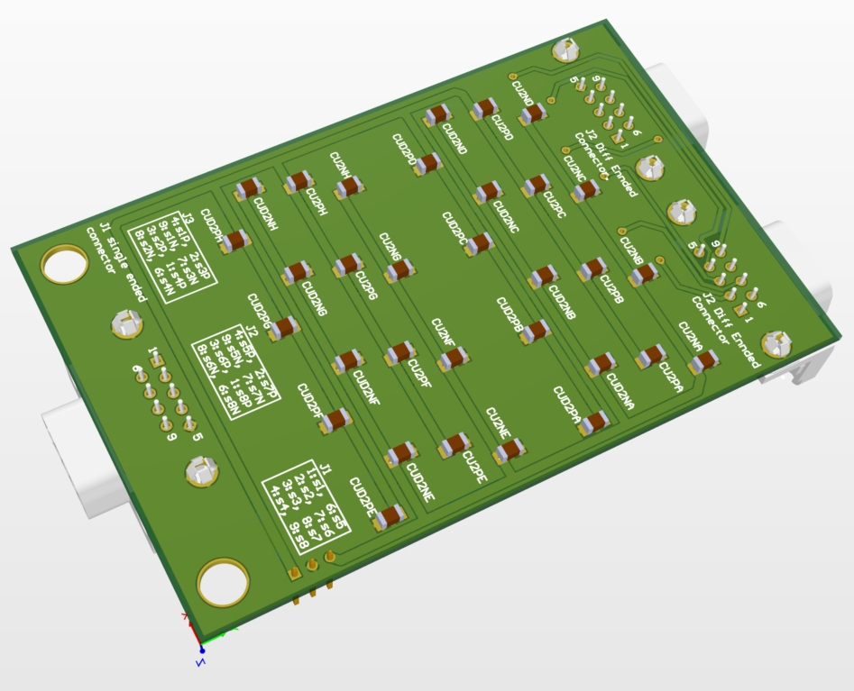
Single-ended to differential-ended PCB design and implementation - University of Western Australia (UWA)
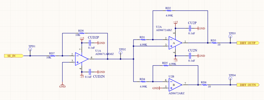
In this project, I showcased my expertise in designing and liaising with PCB manufacturers to develop a solution that utilizes differential signaling. The goal was to enable the transmission of data over long distances while minimizing the detrimental effects of Electromagnetic Interference (EMI).
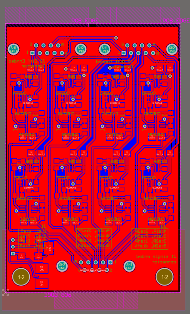
My involvement began with the PCB design, where I meticulously crafted the layout to ensure optimal signal integrity and noise immunity. Special attention was given to the placement of components, particularly capacitors, which were positioned as close as possible to the ICs. This placement strategy reduced electrical noise and enhanced signal quality.
The PCB traces were also carefully optimized to minimize signal degradation and maintain the integrity of the data being transmitted. Factors such as trace width and spacing were taken into consideration to ensure reliable signal propagation over long distances.
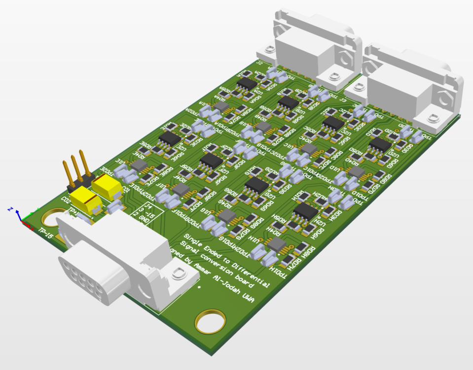
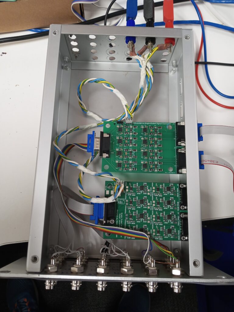
After finalizing the PCB design, I proceeded to oversee the enclosure design. The objective was to create a housing that not only protected the PCB and its components but also facilitated efficient signal transmission. Factors such as material selection, grounding techniques, and EMI shielding were meticulously considered to maintain signal integrity and minimize external interference.
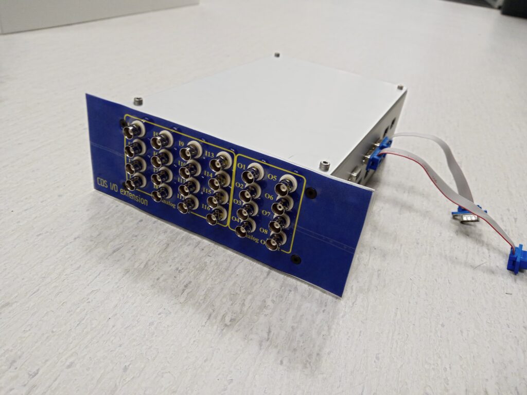
Next, I focused on the front panel implementation. With a keen eye for user experience, I designed an intuitive interface that provided seamless interaction. Attention was given to the placement of connectors, such as BNC, to ensure convenient and reliable connectivity. Clear labeling and ergonomic design elements were incorporated to enhance user-friendliness.
Additionally, I took charge of managing the assembly of components. This involved coordinating with suppliers to ensure the availability of necessary parts and overseeing the entire assembly process. By closely monitoring the assembly, I ensured that all components were correctly placed and connected, minimizing the risk of any potential issues.
Throughout the project, I remained actively involved in testing and quality assurance. Rigorous tests were conducted to validate the functionality and reliability of the PCB boards. Any issues discovered during testing were promptly addressed, guaranteeing a robust and dependable final product.

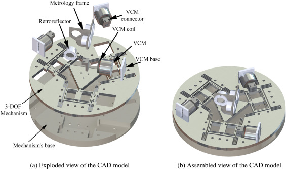
Modeling and a Cross-Coupling Compensation Control Methodology of a Large Range 3-DOF Micropositioner - Robotics and Mechatronics Research Laboratory (RMRL)
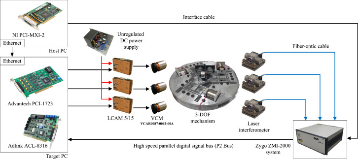
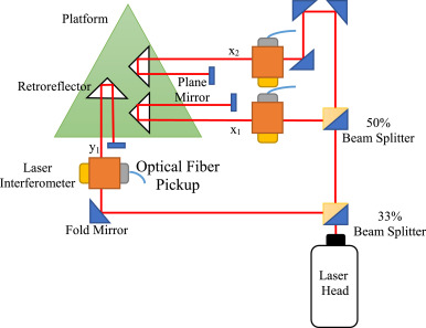
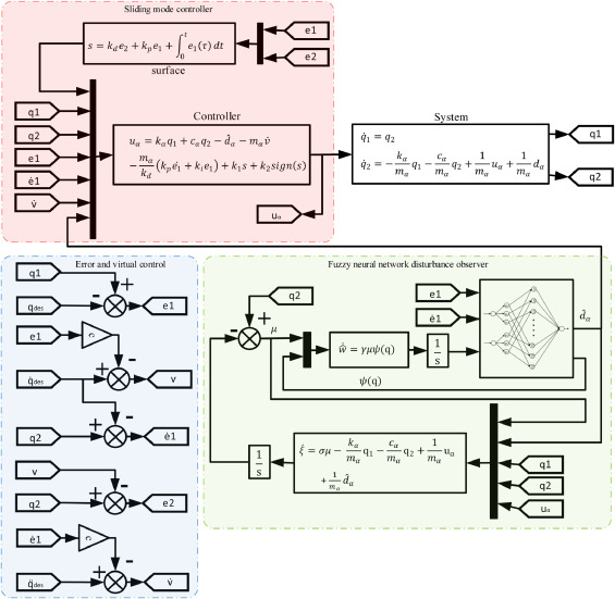
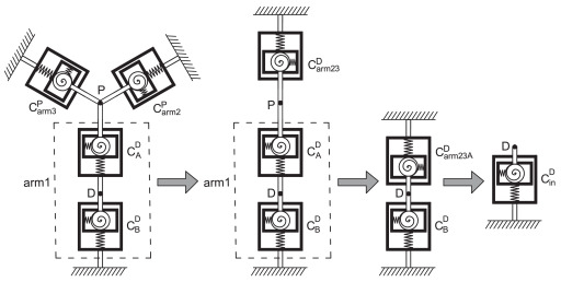
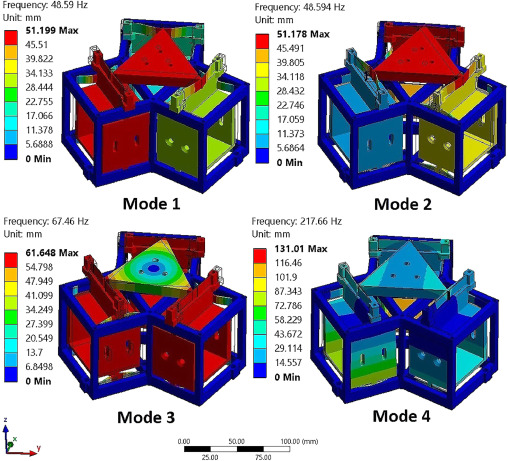
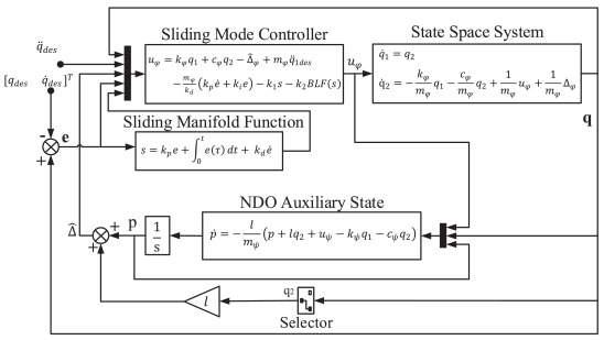
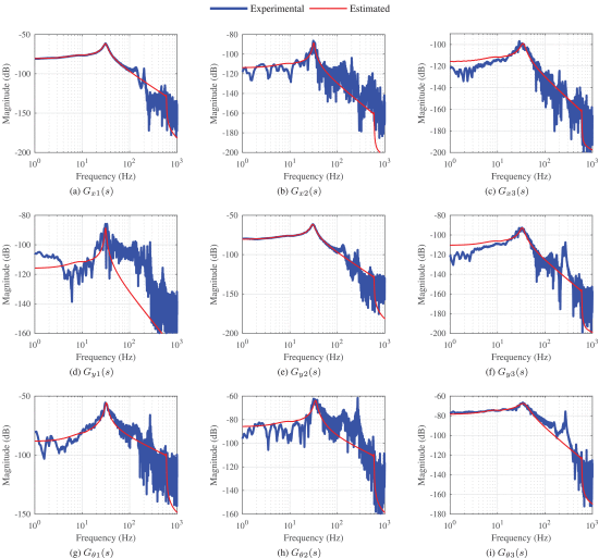
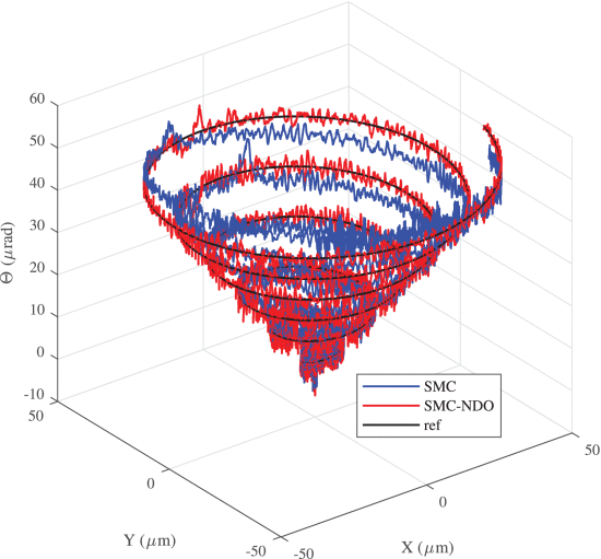
In this project, complex challenges related to parasitic motions and cross-axis coupling in high accuracy, large range, 3-DOF micropositioning mechanisms were tackled. A novel approach was introduced where parasitic motions were reduced using constrained prismatic joints, and systematic analytical modeling was leveraged to understand and design the mechanism’s kinematics, compliance, stiffness, and dynamic models. The crux of the methodology was the application of a backstepping sliding mode control method integrated with an adaptive fuzzy neural network disturbance observer. This advanced control method enhanced motion resolution and tracking performance while effectively mitigating the cross-axis coupling issues, as validated through computational finite element analysis and real-time experimental tests.
More information can be found here.


A Fuzzy Disturbance Observer Based Control Approach for a Novel 1-DOF Micropositioning Mechanism - Robotics and Mechatronics Research Laboratory (RMRL)
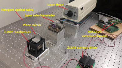
This project introduces a novel, compact, large range 1-DOF micro manipulation mechanism that boasts a high positioning resolution of around 40 nanometers, using leaf flexures in a modular multilayer design configuration for a wide range of motion with a high natural frequency. The modularity of the design positions it as a building block for constructing higher DOF mechanisms. Advanced computational analysis validated the mechanism’s static and dynamic responses, verifying its potential for low flexures stress, high natural frequency, and large workspace. The core of the control technique was the observer-based Sliding Mode controller (SM), enhanced with an adaptive Fuzzy Disturbance Observer (SM-FDO) to optimize tracking performance precision. The design implementation involved 3D printing technology and a Voice Coil Motor (VCM) for large displacement actuation. Experimental results substantiated the robustness and superior tracking performance of the SM-FDO against another implemented robust control technique (H∞).
More information can be found here.
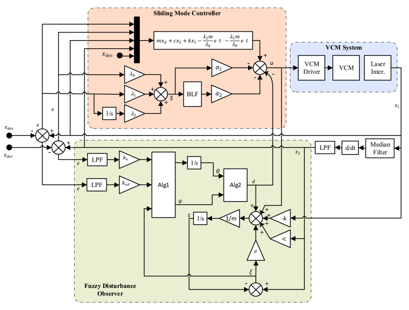
Design, Modeling, and Control of 3-DOF Micro Positioning Stage Utilizing 3D Printing Technology - Robotics and Mechatronics Research Laboratory (RMRL)
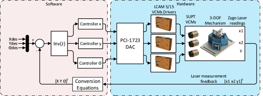
In this project, a compact, large range 3-DOF micropositioning stage was proposed, aiming to address the issues of large footprint and low motion accuracy in existing mechanisms. This innovative design adopts leaf springs for a fully compliant mechanism and utilizes three enclosed Voice Coil Motors (VCMs) for actuation, achieving a large workspace and high motion accuracy without sacrificing compactness. Analytical models and a prototype were developed to assess statics, dynamics, and feedback performance, with a unique laser-based sensing approach devised to measure the 3-DOF motion. Additionally, a robust control technique was implemented to enhance tracking performance. Results indicated that this design successfully integrates a large workspace, high resolution, and superior tracking performance in a compact form.
More information can be found here.
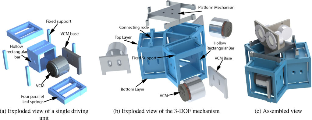
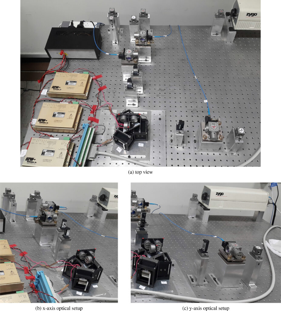
Modernization of XR 4000 Mobile Robot: Hardware and Programming Upgrades - Robotics and Mechatronics Research Laboratory (RMRL)
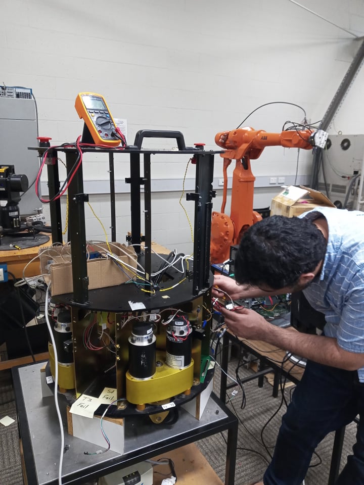
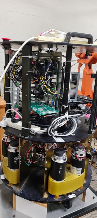
Over the course of this project, my aim was to breathe new life into the XR 4000 mobile robot – a model that, while still boasting significant capabilities, required a technological uplift to meet the demands of modern robotics applications. The initial task was a comprehensive hardware upgrade. I replaced the existing onboard computer with a cutting-edge motherboard, designed to deliver substantial computational power while optimizing energy use. This component was crucial to facilitate advanced operations and to improve the robot’s runtime. Next, a Linux-based operating system was installed, providing a robust and flexible platform for further development. The open-source nature of Linux allowed for customizable kernels and vast library support, streamlining the programming process. The XR 4000’s motion control system also underwent a major transformation. I replaced the original motion control card and motor drivers to enhance the robot’s maneuverability and precision. This allowed the robot to navigate complex environments more efficiently and reliably. To wrap up the hardware upgrades, I took on the programming of the XR 4000 using C++. My focus was to enable manual and remote control of the robot’s motion. With an efficient combination of libraries and custom-written algorithms, I was able to create an intuitive control system, allowing operators to navigate the robot with ease and precision.
The fixing process and code can be found on my GitHub page: https://github.com/ammaraljodah/XR4000/tree/main
Development and Evaluation of a Compact Stick-Slip Linear Actuator for Precision Instruments - University of Western Australia (UWA)
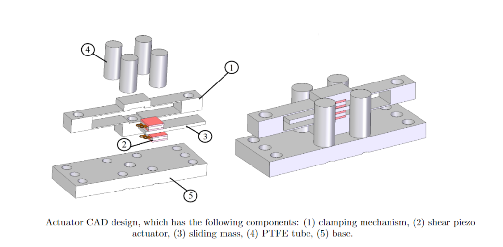
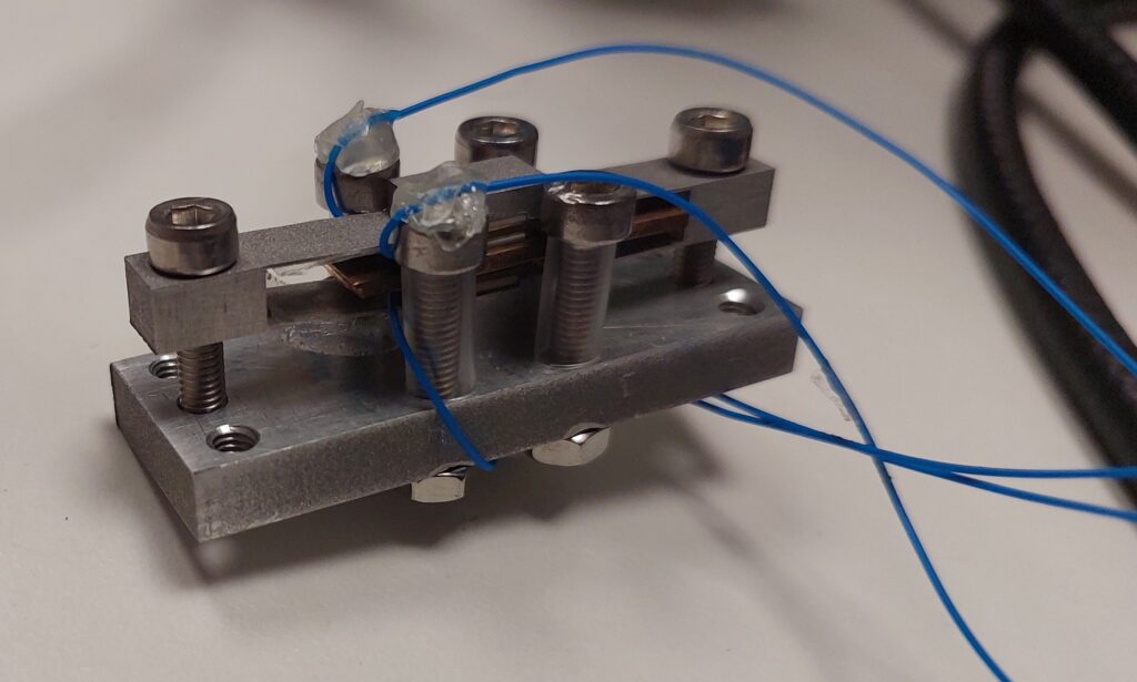
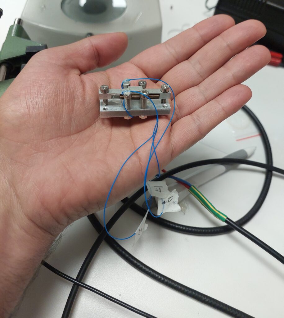
This project centered on the design, implementation, and characterization of a compact stick-slip linear actuator intended for precision instruments. This novel piezoelectric-based linear actuator was specifically designed to address the needs of remote center-of-mass adjusters in scientific devices such as beam-balanced rotation accelerometers. The unique design featured a simplified flexure-based preloading clamping mechanism, reducing the complexity, cost, and orientation restrictions typically associated with similar devices that utilize multiple piezo elements. Moreover, the new design is versatile, capable of operating in any direction with just two actuators and a single driving signal. Both theoretical and experimental studies confirmed the actuator’s ability to produce precise motion in both horizontal and vertical directions. The presented solution demonstrated greater cost-efficiency compared to traditional bionic actuators, marking a significant advancement for precision instruments.
Experimental Verification and Comparison of Different Stabilizing Controllers for a Rotary Inverted Pendulum - Southern Illinois University Carbondale (SIUC)
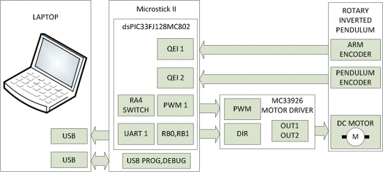
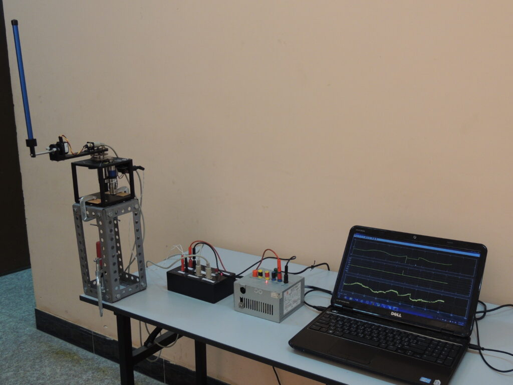
In this project, the primary approach adopted was the use of an energy-based method for the pendulum swing-up and a state feedback controller to maintain the pendulum in an upright position. Moreover, a mixed H2/H∞ state feedback controller was utilized to stabilize the pendulum with reduced oscillations. The outcomes were assessed against the standard full-state feedback and Linear Quadratic Regulator (LQR). A Quanser rotary inverted pendulum served as the experimental setup for the project. Importantly, the controllers were implemented in real-time using the Microstick II with dsPIC33FJ128MC802 and Simulink embedded target for Microchip®, which eliminated the need for a PC during the real-time operation apart from logging the displaying the data. Results demonstrated that the mixed H2/H∞ controller effectively minimized oscillations and maintained the stability of this highly nonlinear and unstable system.
More information can be found here.
Robust Speed Control Methodology for Variable Speed Wind Turbines - Robotics and Mechatronics Research Laboratory (RMRL)
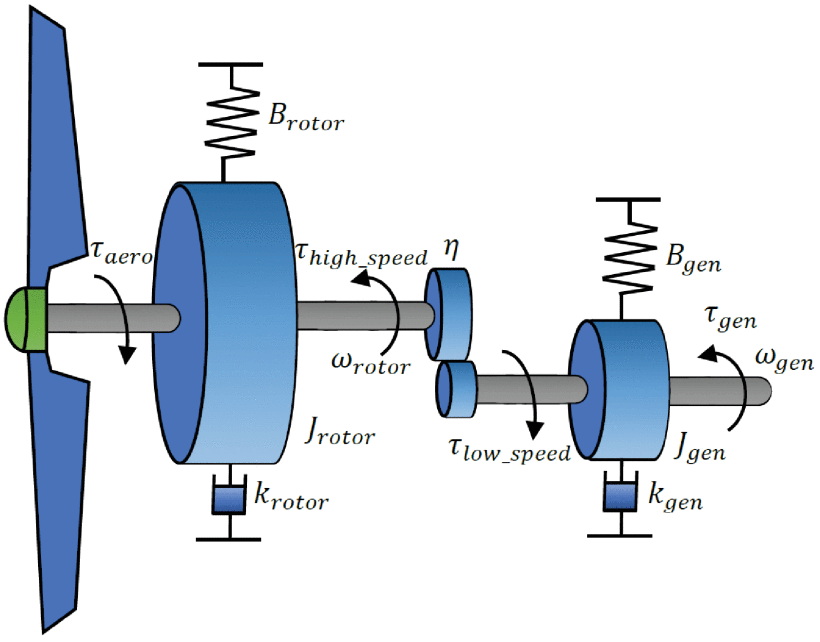
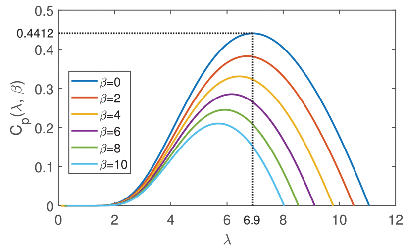
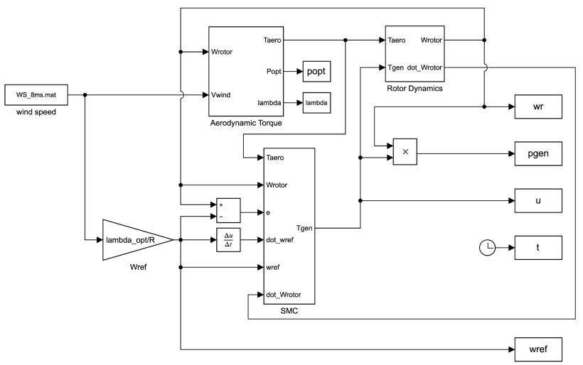
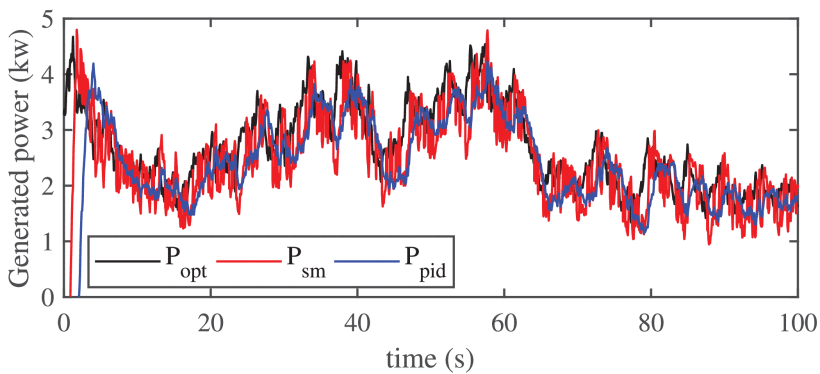
In this project, I aimed to enhance wind turbine efficiency, thereby reducing energy production costs. Given the complex nonlinear dynamics and unpredictable operational conditions of wind turbines, I devised a robust control strategy based on sliding mode and an adaptive fuzzy disturbance observer for effective speed tracking in variable speed wind turbines. After deriving a nonlinear mathematical model to describe wind turbine dynamics, I utilized this model to derive the control methodology, ensuring stability and robustness. This methodology aimed to track optimal wind speed for maximum energy extraction, with stability conditions affirmed using Lyapunov stability theory. A comparative simulation study demonstrated the methodology’s robustness and superior tracking capabilities, outperforming classical control methods in power extraction. This work underpins the potential of robust control methodologies in optimizing energy extraction from variable speed wind turbines.
More information can be found here.
Seismic Isolation Control in of an Optical Table - Gingin High Optical Power Facility (HOPF)
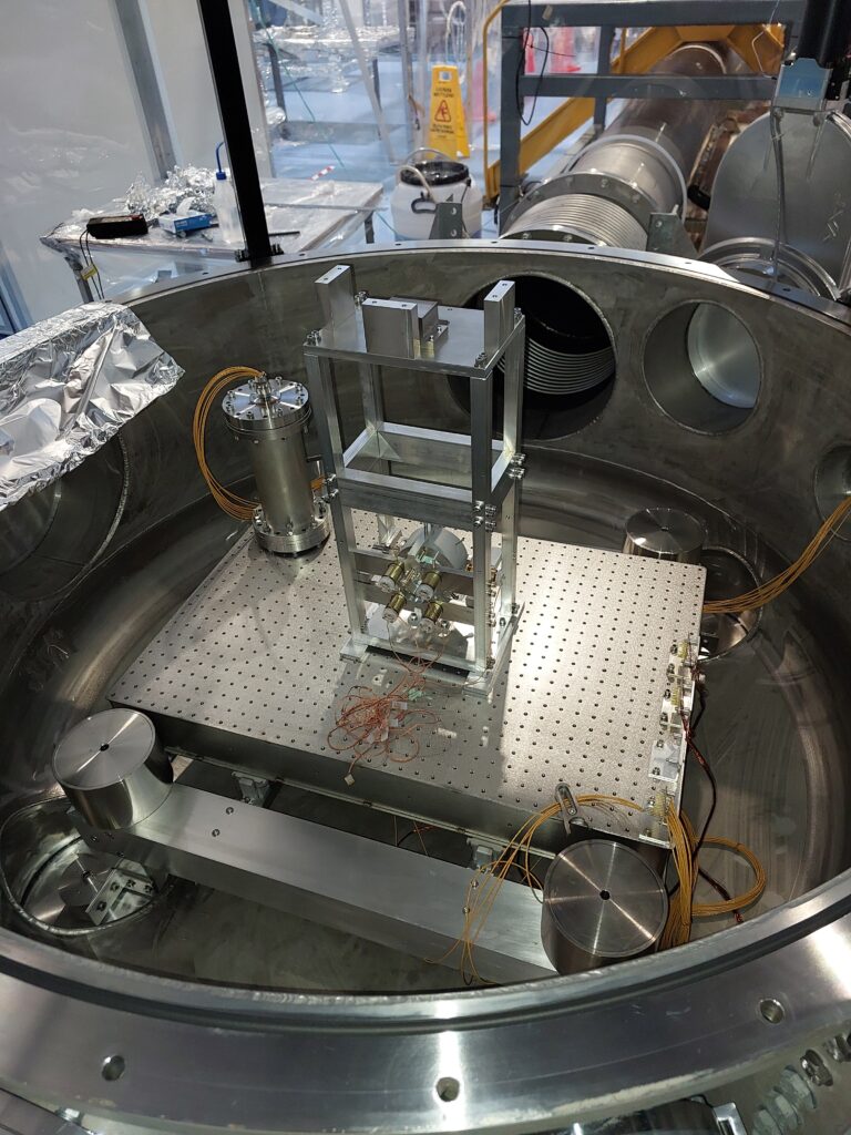
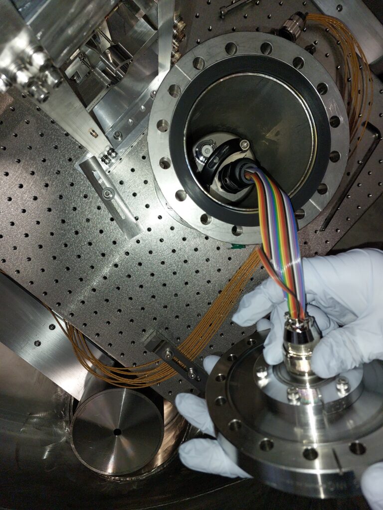
In this project, I worked on seismic isolation control for the UWA high laser power facility. My responsibilities included conditioning the signal from a seismometer and designing and implementing a feedback control loop in a control and data acquisition system (CDS). I developed a signal conditioning circuit to amplify, filter, and digitize the seismometer’s output signal. For the feedback control loop, I conducted system analysis, modeling, and designed a control algorithm incorporating lead lag filters. I implemented the control algorithm in a CDS, utilizing high-speed data acquisition, real-time control, and interfacing with piezo actuators to drive a table in three degrees of freedom. Through comprehensive testing and validation, I successfully demonstrated the system’s effectiveness in isolating the table from seismic vibrations.
Shadow Sensor PCB Design and Implementation - Gingin High Optical Power Facility (HOPF)
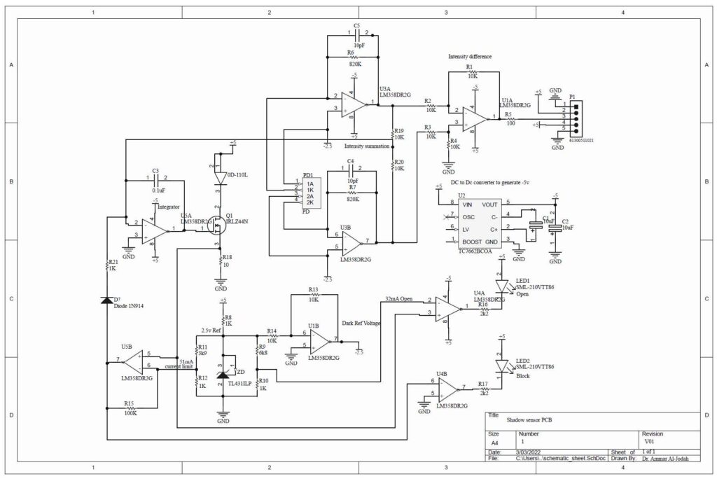
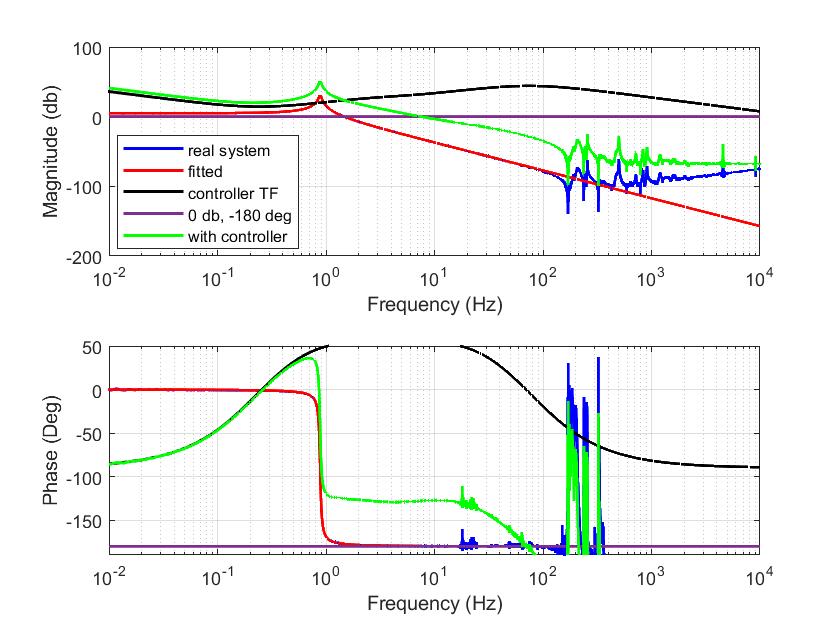
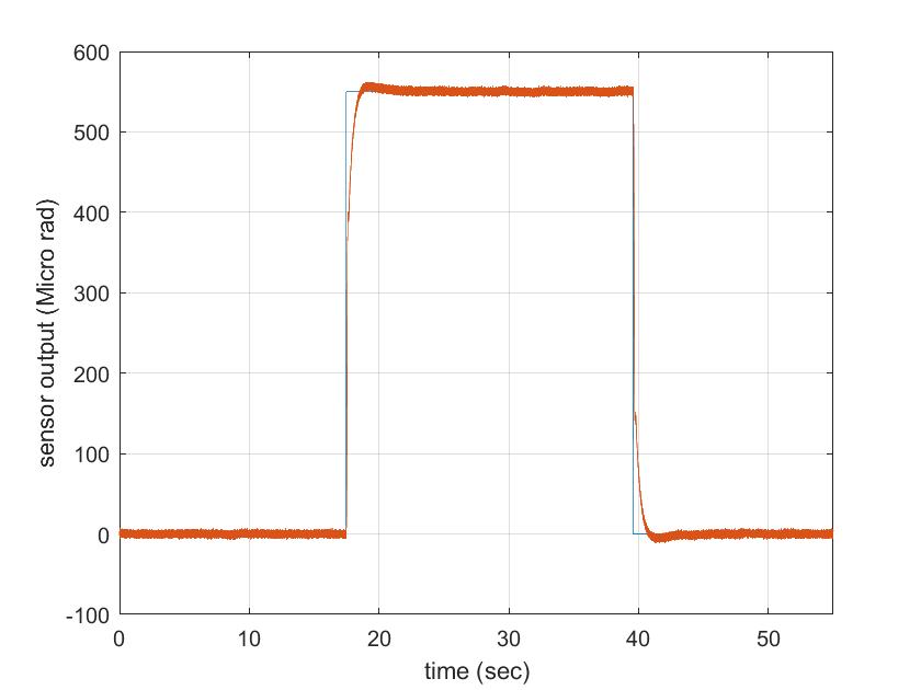
Tiltmeters, devices designed to accurately detect tilt angles, operate by measuring the tilt of the beam balance at the pivot point. These instruments commonly employ optical walk-off sensors for tilt angle detection. While these sensors boast high sensitivity, they also possess a relatively low dynamic range. To mitigate this, mechanical motion limits are often implemented to prevent excessive displacement of the beam balance beyond a pre-determined range. Exceeding this range impacts the number of bounces between the mirrors of the walk-off sensor and could ultimately cause the sensor to lose its lock. However, calibration of these mechanical stops for vacuum operation presents considerable challenges. Furthermore, the use of mechanical motion limits can inadvertently cause the tiltmeter to adhere to these limits due to adhesive forces, impeding its movement. To address these challenges, the project proposes the implementation of a shadow sensor designed to feed back the tilt displacement to a coarse control loop. This loop servos the beam balance to a neutral position before it reaches the mechanical limits, thereby keeping the walk-off sensor locked and allowing for a more substantial gap for the mechanical stops. A specially designed shadow sensor, mounted beneath the tilt sensor, was incorporated to detect and feedback tilt displacement. When used within a feedback loop, this sensor demonstrated high accuracy, significantly improving the system’s overall servo capability.


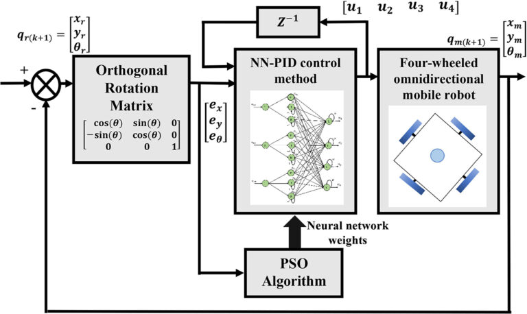
Optimized Neural Network PID Control Approach for a Four Wheeled Omnidirectional Mobile Robot - Robotics and Mechatronics Research Laboratory (RMRL)
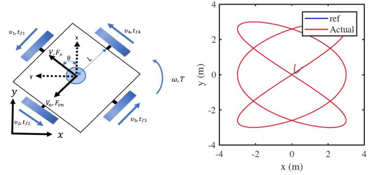
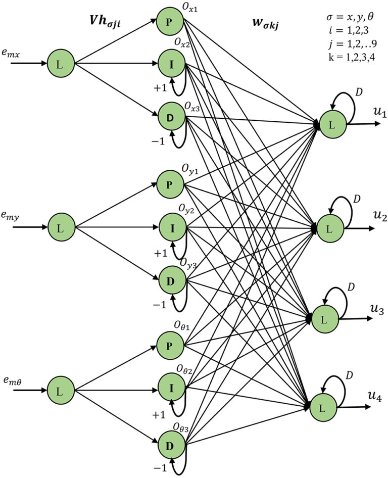
This project address the rising need for advanced automation using mobile robots. Omnidirectional mobile robots, notable for their exceptional maneuverability and ability to easily track complex trajectories, have seen increased interest. However, the complexity of their dynamic model presents significant control challenges. To overcome these, I developed a kinematics and dynamics model for a four-wheeled omnidirectional robot and introduced an intelligent Proportional Integral Derivative (PID) neural network control methodology for trajectory tracking. I utilized the Particle Swarm Optimization (PSO) algorithm to optimize the controller’s weights. Simulation studies using Matlab package affirmed the proposed control method’s accuracy in performing trajectory tracking tasks.
More information can be found here.
Antlion optimized robust control approach for micropositioning trajectory tracking tasks - Robotics and Mechatronics Research Laboratory (RMRL)
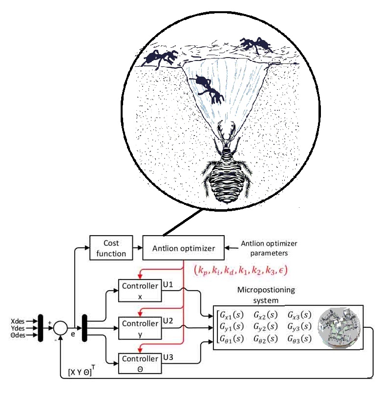
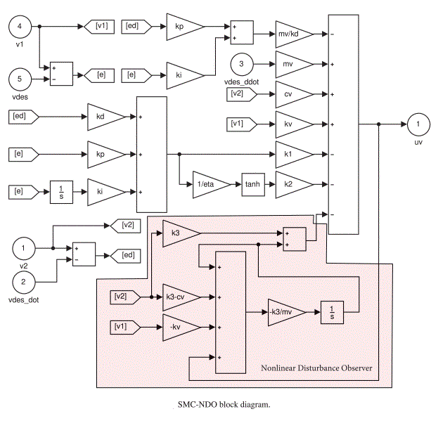
This project addresses the issues of motion accuracy in 3-DOF micropositioning stages, affected by cross-couplings, model uncertainty, and external disturbances. I developed a systematic model of a 3-DOF precision micropositioning stage and proposed an optimized robust control methodology based on disturbance estimation. This novel approach involved a nonlinear disturbance observer-based sliding mode control, capable of estimating and compensating unavoidable cross-couplings. To ensure system stability, I performed a comprehensive stability analysis and utilized the Antlion Optimizer algorithm for automatic tuning of the control parameter, eliminating the need for manual tuning. Experimental results demonstrated the superiority of the proposed control method over the classical sliding mode approach in tracking complex trajectories.
More information can be found here.
Development of Simulink Realtime Drivers and Blocks for Advantech PCI Cards - Robotics and Mechatronics Research Laboratory (RMRL)
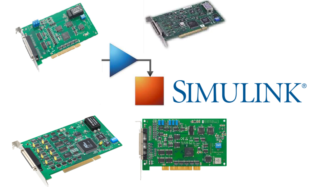
As an engineer passionate about embedded systems and automation, I embarked on a project to create Simulink Realtime drivers and blocks for Advantech PCI cards, aiming to integrate software simulation with real-time hardware control. Through my work on the PCI-1716, PCI-1723, PCI-1720, and PCI-1713 — diverse hardware cards frequently employed in industrial automation and control systems — I strived to streamline the process for engineers to design, simulate, and implement control systems using MATLAB and Simulink. The project began with an understanding of the technical details of each PCI card, followed by the design and development of the necessary drivers and Simulink blocks. I rigorously tested them to ensure their effective performance in real-time simulations. This project not only culminated in reliable tools that enhance MATLAB and Simulink workflows but also broadened my insights into the complexities of embedded systems development, reinforcing my skills in hardware interfacing, real-time simulations, and software development. I am proud to share the GitHub repositories of my project:
PCI-1716
PCI-1723
PCI-1720
PCI-1713
These repositories are open for everyone to explore, clone, or contribute to, with the intention of expanding the potential of MATLAB and Simulink for real-time control systems design and implementation.
Development of a Simulink Real-Time Driver for Zygo Laser Displacement Measuring Interferometers - Robotics and Mechatronics Research Laboratory (RMRL)
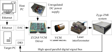
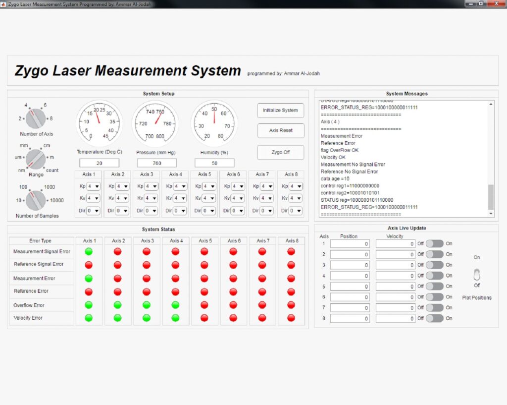
In this project, my main objective was to develop a software structure that enables real-time integration of Zygo laser displacement measuring interferometers with MATLAB, leveraging Simulink real-time software. By utilizing Simulink’s user-friendly interface and automatic code generation feature, I aimed to accelerate the development process. I used the C language, commonly used for programming MATLAB Level-2 S-functions, to write the low-level driver for the Zygo system. This driver code used the P2 communication protocol to communicate with the Zygo system and read the data. Through the integration process, I developed a Windows-based software for system initialization and real-time measurement. This optimized software structure significantly improved control, measurement, and overall system performance. By utilizing Simulink’s capabilities, I was able to streamline the development workflow, reducing the time required for implementation and testing. Further, I designed a Human Machine Interface (HMI) for the system to enable users an easy monitoring and configuration of the laser system. I have made the project available on GitHub (https://github.com/ammaraljodah/Zygo), providing a platform for others to access and benefit from the work done.
The Github project can be found here: https://github.com/ammaraljodah/Zygo
